Proxmark3 community
Research, development and trades concerning the powerful Proxmark3 device.
Remember; sharing is caring. Bring something back to the community.
"Learn the tools of the trade the hard way." +Fravia
You are not logged in.
Announcement
Time changes and with it the technology
Proxmark3 @ discord
Users of this forum, please be aware that information stored on this site is not private.
Pages: 1
#1 2009-06-24 11:39:44
- adam@algroup.co.uk
- Contributor
- From: UK
- Registered: 2009-05-01
- Posts: 203
- Website
LF voltage
The PM3 manual says "The tune command should return a value of about 20V for a properly tuned antenna":
https://www.lafargue.name/article2751.html
Is this for 125 or 134, and what should the other one be?
Mine currently looks like this, so I'm not sure whether to adjust up or down...
> tune
# LF antenna @ 11 mA / 14501 mV [1273 ohms] 125Khz
# LF antenna @ 31 mA / 37194 mV [1187 ohms] 134Khz
# HF antenna @ 0 mA / 64 mV [235 ohms] 13.56Mhz
Offline
#2 2009-06-24 21:14:00
- d18c7db
- Contributor
- Registered: 2008-08-19
- Posts: 292
Re: LF voltage
First off, your antenna may work well enough the way it is. Test it on a tag and see.
Ideally you want to bring those two voltage values close to each other, at the moment your antenna looks like it's tuned towards the higher frequency. Use the losweep, losamples and plot commands and note the numeric value under the peak. That gives you the antenna tuned frequency like so freq = 12M/(value+1)
Try removing a couple of turns from the coil and recheck the values, if the frequencies move toward each other, continue removing turns, otherwise you might have to add turns.
Offline
#3 2009-06-25 10:43:05
- adam@algroup.co.uk
- Contributor
- From: UK
- Registered: 2009-05-01
- Posts: 203
- Website
Re: LF voltage
Thanks for you help, and sorry if I'm being dim but I'm not really following, not being an electronics guy...
Here is a screenshot:
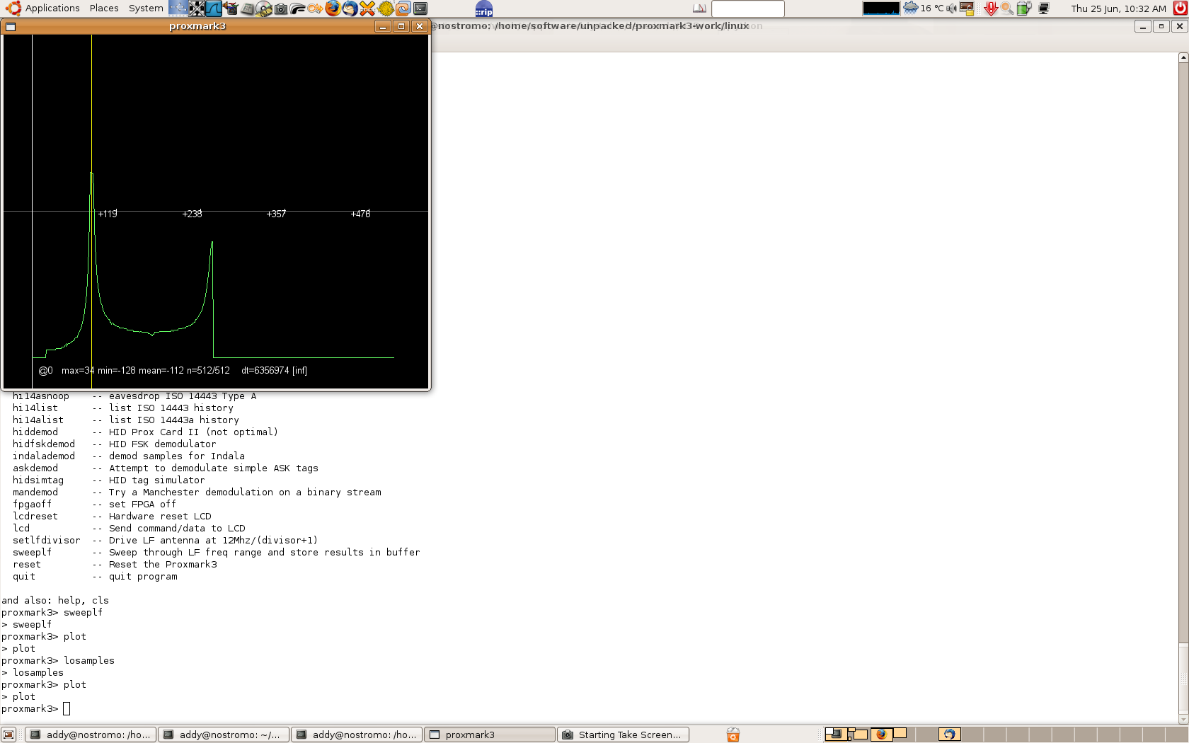
What is that telling me?
Offline
#4 2009-06-26 03:21:15
- ryan
- Contributor
- Registered: 2009-06-17
- Posts: 36
Re: LF voltage
Alright, I'm just trying to get the hang of all of this as well, so please correct me if I'm wrong.
From what I gather, plugging the dt between zero and the time at the max value into the formula d18c7db gave us will give you the optimal frequency that your antenna is currently tuned to. I'm not sure why your dt value is so wacky, but when i click on the peak (in the windows version) while trying to tune my antenna, it gives me about 92. So 12,000,000/92 = 130434.78, which I believe is the Hz value of the peak. This is a pretty decent balance between 125khz and 134khz. If you're shooting for 125khz, you'd probably want the spike to be at 96, and ~89.5 for 134khz.
If you want to increase the dt of the spike, add more wire. Remove wire to decrease the dt.
-Ryan
Last edited by ryan (2009-06-26 16:04:39)
Offline
#5 2009-06-26 15:14:17
- d18c7db
- Contributor
- Registered: 2008-08-19
- Posts: 292
Re: LF voltage
Yeah your dt value is way off, it should be around 90something mark. Maybe it's a bug with the linux client. Ryan is correct regarding the rest. Have you tried to read a tag with the antenna the way it is? It may just work well enough, you don't have to have it perfect.
Offline
#6 2009-06-26 18:31:49
- adam@algroup.co.uk
- Contributor
- From: UK
- Registered: 2009-05-01
- Posts: 203
- Website
Re: LF voltage
Yes, it works fine as it is but if there's something wrong with the client I'll try to fix it... I'll take a closer look in the next few days....
Thanks for the help!
Offline
#7 2009-07-08 01:22:01
- adam@algroup.co.uk
- Contributor
- From: UK
- Registered: 2009-05-01
- Posts: 203
- Website
Re: LF voltage
OK, I've fixed the dt problem in the linux client. It was that CursorAPos and CursorBPos were not being initialised, so they would start with a random high value. I must confess I am not a .cpp puppy, so the way I initialised them may be totally incorrect... someone please feel free to correct it if you know the 'proper' way (or tell me how and I'll do it)...
BTW, I also added the display of Cursor A and B positions, but since I don't have a Windows dev environment I didn't want to tamper with it's code so maybe someone who does could bring them into line?
Thanks!
Offline
#8 2009-07-08 02:11:20
- samy
- Contributor
- From: los angeles, california
- Registered: 2009-06-18
- Posts: 148
- Website
Re: LF voltage
Damn pup.py ![]()
I've tested and checked in your update to the Windows source, works fine.
I've also checked in an updated command.cpp -- it wasn't compiling in Windows. You may want to confirm my change is ok, it's line 706 in command.cpp in function CmdLoCommandRead:
- strcpy(&c.d.asBytes + strlen(c.d.asBytes),dummy);
+ strcpy((char *)&c.d.asBytes + strlen((char *)c.d.asBytes), dummy);
Offline
#9 2009-07-08 03:18:25
- adam@algroup.co.uk
- Contributor
- From: UK
- Registered: 2009-05-01
- Posts: 203
- Website
Re: LF voltage
Great, thanks. Yep, that compiles fine under linux...
Oh, and since the object of the exercise was to determine the resonant frequency of the antenna, I've modded 'sweeplf' to do it for you:
proxmark3> sweeplf
> sweeplf
#db# Antenna resonates at:
#db# 134.831 kHz
Offline
#10 2009-07-08 07:10:17
- samy
- Contributor
- From: los angeles, california
- Registered: 2009-06-18
- Posts: 148
- Website
Re: LF voltage
Nice!
Well I guess I shouldn't complain because it works (at least for the 125Khz tags I've tested), but my voltages aren't great either. I'm working on my portable antenna but I suppose these are good enough, yes?
# LF antenna @ 11 mA / 14099 mV [1273 ohms] 125Khz
# LF antenna @ 23 mA / 28466 mV [1187 ohms] 134Khz
# HF antenna @ 21 mA / 5091 mV [235 ohms] 13.56Mhz
Offline
Pages: 1